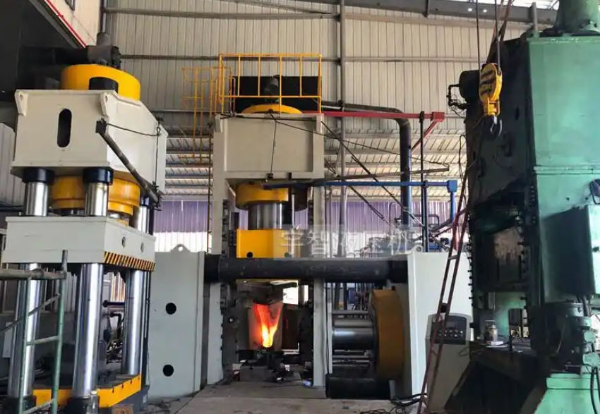
Forging Tooth Production Process — Forging Tooth Forming Hydraulic Press
The forging tooth forming hydraulic press is the core machine in the forging tooth production process. By applying external force to the metal raw materials using this press, it causes plastic deformation of the metal, changing the shape and size of the billet while improving its internal structure and mechanical properties, resulting in the final formed forging tooth. Forging eliminates defects such as porosity generated during the metal smelting process, optimizes the microstructure, and since it preserves the complete metal flow line, the mechanical properties of forgings are generally superior to castings made from the same material. Therefore, although the forging tooth production process is costlier, it ensures the highest quality for the forged teeth. The forging tooth is a crucial component on excavators, similar to human teeth, and is an easily worn part, requiring continuous production and processing to meet demand.

Forging Tooth Production Process:
The forging tooth production process includes the following steps:
- Blanking — Heating — Pre-forging with Roller Press — Upsetting Process — Closed Die Compound Hydraulic Press Extrusion — Compound Punching and Marking Process — Post-forging Heat Treatment.
The closed-frame compound hydraulic press extrusion ensures that the forging tooth undergoes three-way compressive stress, improving the internal quality of the forging. Additionally, the compound punching and marking process reduces one step, lowers labor intensity, and enhances production efficiency.
Overview of the Forging Tooth Forming Hydraulic Press Performance and Structure:
Due to the different sizes and weights of the forging teeth, there are various tonnage models of forging tooth forming hydraulic presses. The commonly used tonnages are 1000 tons, 2000 tons, 4000 tons, and 5000 tons, with the 5000-ton forging tooth forming hydraulic press being the most commonly used. Forging presses of different sizes can forge both small and large forging teeth.
The design of the main machine structure incorporates the advantages of products from major domestic and international manufacturers, as well as advanced technology. The entire machine is optimized using finite element design and industrial design, focusing on overall performance, usability, durability, high stiffness, and reliability. At the same time, the machine's overall shape and color scheme are designed to be aesthetically pleasing.
Machine Body:
The body is composed of structural components welded from steel plates, which are vibrationally aged to eliminate welding stress. The lower crossbeam, columns, and upper crossbeam are pre-tensioned using tension rods (hydraulic pre-tensioning) to form a combined frame. The middle of the machine body is equipped with a slide, with a slanted wedge-type four-corner, eight-face guide for the slide. The slide guide plate is made of a composite material (A3+CuPb10Sn10), and the guides on the column are removable.
Hydraulic Cylinder:
The main 2000-ton downward press cylinder is implemented with a single cylinder, using high-quality 45# carbon steel forgings. The surface is treated with medium-frequency quenching, achieving hardness between HRC48-55, and is chrome-plated (5-10μm), ensuring long service life. The piston cylinder is also made of high-quality 45# carbon steel forgings, with the inner surface processed by rolling. The hydraulic cylinder provides sufficient strength and rigidity, and the main oil cylinder uses imported sealing elements to ensure reliable sealing performance.
The 2800-ton side cylinders and 200-ton top cylinders use the same manufacturing process as the 2000-ton main cylinder.
Electrical Control System:
The electrical system consists of the power circuit and control circuit. The power circuit is 380V, 50HZ, and is responsible for the starting, stopping, and protection of the oil pump motor. The core functions of the control section are handled by a programmable logic controller (PLC). Based on process requirements, commands from the main control components (such as selection switches and buttons) are processed according to signals detected by limit switches and pressure relays, driving hydraulic pilot valves and other devices to control the pressure and displacement of the hydraulic actuators (oil cylinders), thus completing the production process.
Hydraulic Control Section:
The hydraulic power system consists of the power control system, various valves, and hydraulic manipulation boxes, providing power to the main machine and enabling its control. The hydraulic station is located on the right side of the main machine.
Safety Protection Measures for the Forging Tooth Forming Hydraulic Press:
- Stop and Emergency Stop Buttons: In case of an anomaly, pressing the “Stop” button halts pressure and work completely. Pressing the “Emergency Stop” button will stop all operations, including the motor.
- Dual-Hand Operation Button: The dual-hand synchronization time limit for downward motion is 0.5 to 1 second.
- Hydraulic Double Support Safety Circuit: To prevent uncontrolled downward movement of the slide, a hydraulic double-support valve circuit is set in the lower chamber of the piston-type main cylinder, ensuring safety. A hydraulic interlock circuit ensures that the main cylinder piston cannot move downward unless the support safety valve is open.
- Overload Protection: The hydraulic system is equipped with a safety valve to ensure the press does not operate under overload conditions, thus preventing damage to the machine.
- Maintenance Platform: The top of the machine is equipped with a maintenance platform, ladder, and safety fencing to ensure the safety of maintenance personnel.