A Deep Dive into the Working Principle and Structure of Tracks
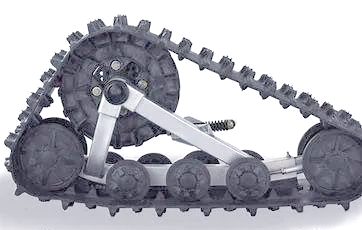
A track is a flexible chain loop driven by the drive wheel, operating around the drive wheel, idler wheel, tensioning wheel, and support rollers. This chain loop consists of key components such as the track plate and track pin. The track pin connects the individual track plates, forming a complete track loop.

Working Principle of the Track
The design of the track plate is ingenious, with holes at both ends that engage with the drive wheel, driving the track to work. In the middle of the track plate, induction teeth are cleverly arranged. These induction teeth not only help align the track’s direction but also effectively prevent the track from detaching during turns or when the Excavator tilts. Additionally, the surface that contacts the ground is reinforced with anti-slip ribs (commonly called tread patterns). This design not only enhances the strength of the track plate but also significantly improves the track’s grip on the ground.

Design and Function of the Idler Wheel
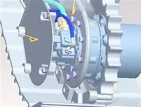
The idler wheel is an essential component of the Excavator. It not only supports the Excavator's weight but also helps align the direction of the track. The internal structure of the idler wheel is intricate, consisting of components such as the hub, wheel disc, rubber tape, ball bearings, axle cover, fixed nuts, and oil-seal cover. Through the combined function of multiple idler wheels, the Excavator's weight is evenly distributed, ensuring a more balanced distribution of pressure from the track on the ground. This design not only improves the Excavator's mobility but also extends its service life.

When the engine's power is transmitted to the drive wheel, the drive wheel rotates in a clockwise direction, driving the track. This driving mechanism creates a mutual force between the track’s contact with the ground and the ground itself. According to Newton’s third law of motion—action and reaction—the track exerts a force on the ground in the horizontal direction, and the ground exerts a reactive force on the track. It is this reactive force that propels the Excavator forward, known as the Excavator’s traction force.

Initially, the developers of Excavators drew inspiration from the track design of agricultural crawler tractors. For example, in 1915, the British "Little Wanderer" Excavator used the tracks of the American "Blauek" tractor. By 1916, the French "Schneider" and "Saint-Chamond" Excavators adopted the tracks of the American "Holt" tractor. After nearly 90 years of development and evolution, the track has become an indispensable part of the Excavator, with continuous improvements in its structure, materials, and manufacturing processes, providing stable support and excellent traction to enable the Excavator to meet the challenges of various combat environments.

Excavator Mobility: Power and Ground Conditions
The mobility of a Excavator is constrained by two key conditions: power conditions and ground conditions. The power condition comes from the engine, which must provide sufficient force to move the Excavator across the ground. Without this power, the drive wheel cannot rotate. The ground condition relates to the force exerted by the drive wheel through the track, which requires the ground’s reactive force (traction) to move the Excavator forward. When the traction force equals the resistance to movement, the Excavator moves at a constant speed. If the traction force exceeds the resistance, the Excavator accelerates; conversely, if the traction force is less than the resistance, the Excavator slows down.