Articles of Category: Default

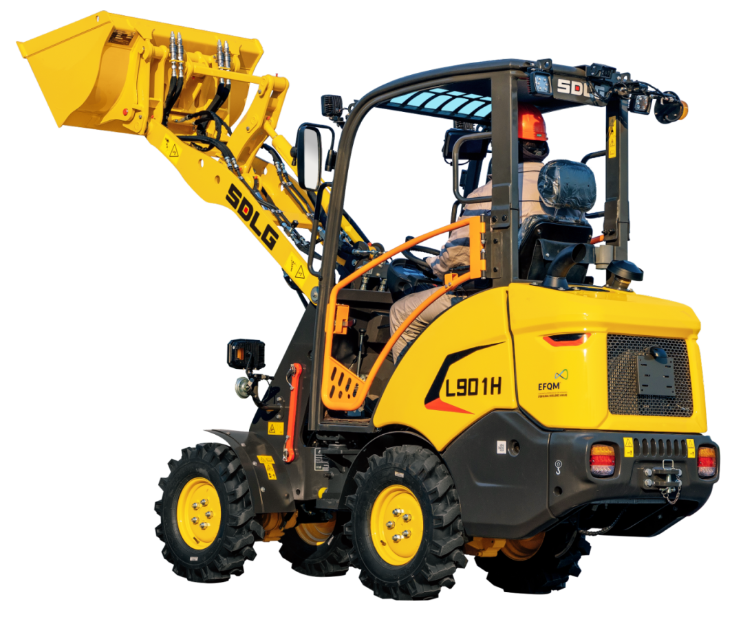
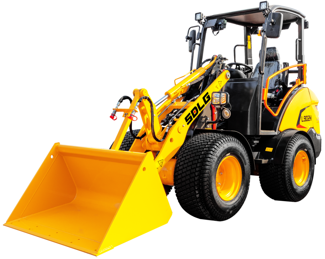
Lingong L901H and L902H Wheel Loaders

Small but Mighty: Unleashing Power with Precision

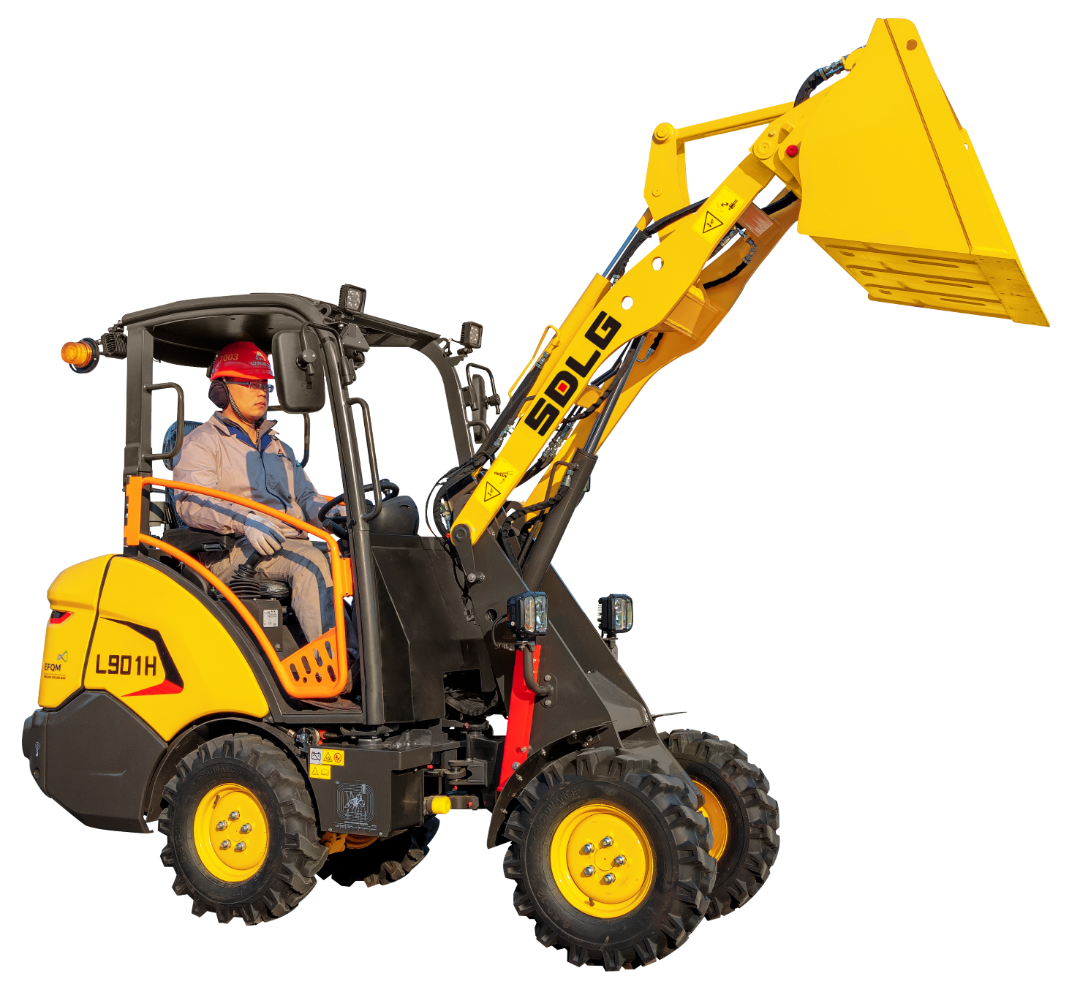
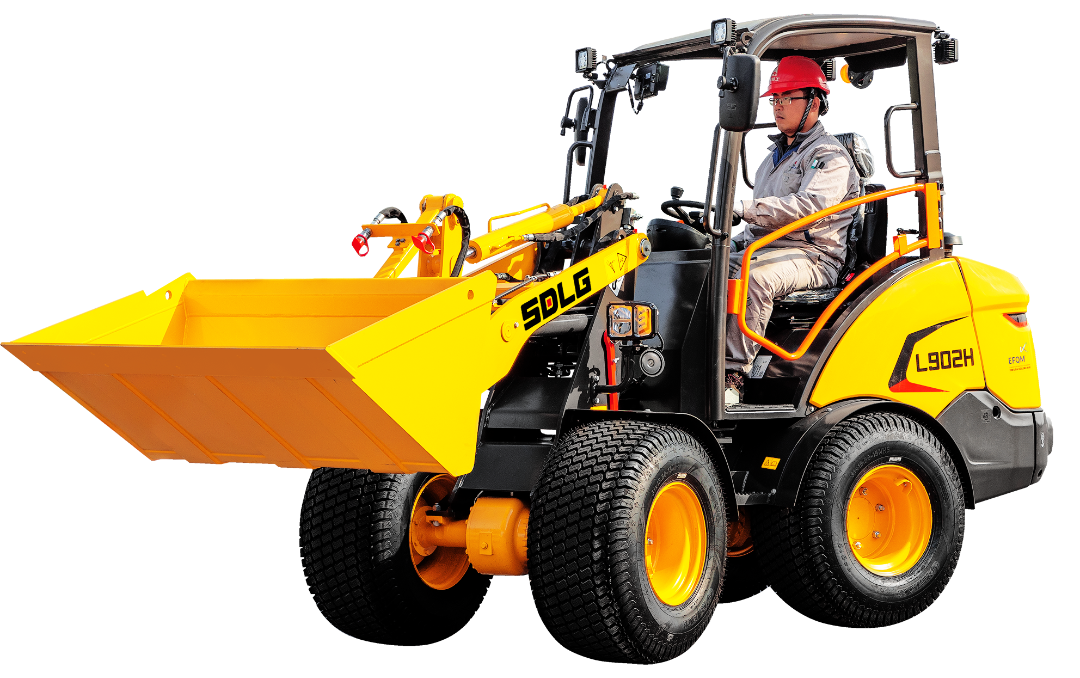
With powerful breakout force in a compact body, the L901H and L902H compact wheel loaders from Shandong Lingong (SDLG) redefine efficiency in the small-tonnage segment. These "mini powerhouses" inherit SDLG’s legacy of high quality and reliability, while incorporating innovative design and outstanding performance to offer users efficient, energy-saving, and safe operation solutions. Whether on small construction sites or in complex working conditions, the L901H and L902H handle it all with ease—demonstrating SDLG's deep technical expertise and keen market insight in the construction machinery industry.
Lingong L901H and L902H Wheel Loaders

Proprietary Technology for a Perfect Balance of Traction and Agility

The L901H is equipped with SDLG’s proprietary drive system, designed to maintain exceptional traction across a variety of terrains—be it soft ground, rugged landscapes, or confined spaces. Its superb adaptability ensures optimal performance in any scenario. The L902H builds on this foundation with enhanced structural design, delivering improved stability and work efficiency, making it especially well-suited for tasks requiring greater loading capacity.
Lingong L901H and L902H Wheel Loaders

Efficient Powertrain: Fuel-Saving and Eco-Friendly

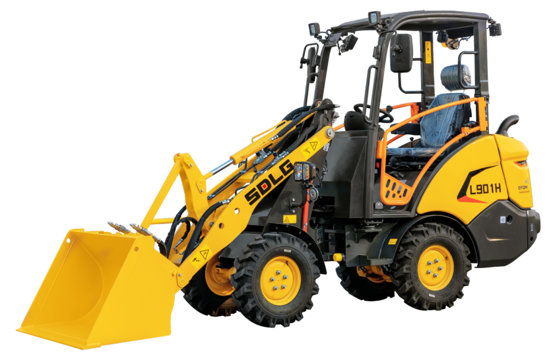
Both models are powered by the Kubota D1703 high-displacement engine with a rated output of 18.2 kW. Renowned for its efficiency and low fuel consumption, this engine operates stably at low RPMs—minimizing vibration and noise while significantly reducing fuel use. This translates into lower operating costs and extended engine lifespan, ensuring reliable performance even during prolonged, high-intensity operations.
Lingong L901H and L902H Wheel Loaders

User-Friendly Maintenance and an Upgraded Operating Experience

SDLG is committed to delivering convenience in both operation and maintenance. The engines in both the L901H and L902H feature multiple access ports, located at the rear and beneath the operator seat, allowing for easy routine maintenance and servicing. This design reduces downtime and boosts machine uptime. Additionally, both models are equipped with ergonomically designed throttle levers, enabling operators to adjust engine speed in real-time based on working conditions—achieving precise control and enhanced efficiency.
Lingong L901H and L902H Wheel Loaders

Certified Safety: Durable, Reliable, and Built to Last

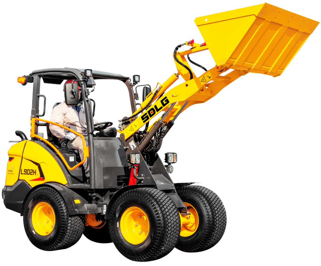
Safety is a top priority. The L901H and L902H have both passed stringent ROPS (Roll-Over Protective Structure) and FOPS (Falling Object Protective Structure) certifications. Their reinforced canopy structures ensure operator safety under challenging work conditions. Constructed with high-strength steel and advanced manufacturing processes, these machines offer exceptional durability and impact resistance—capable of withstanding harsh environments and providing users with dependable long-term support.
Lingong L901H and L902H Wheel Loaders

Specifications Comparison: Meeting Diverse Operational Needs

While both the L901H and L902H share the same core technology and powertrain, they differ significantly in bucket capacity, operating weight, and overall dimensions—catering to the varied needs of different users and job sites.

model L901H L902H
engine Kubota D1703 Kubota D1703
power 18.2 kW 18.2 kW
Bucket Capacity 0.25 m³ 0.35 m³
Operating Weight 1,990 kg 2,400 kg

Overall dimensions

(mm)

4,000 × 1,137 × 2,203  4,120 × 1,338 × 2,282

As a leading player in China’s construction machinery sector, Shandong Lingong continues to place technological innovation and customer-focused design at its core. The launch of the L901H and L902H compact loaders reflects SDLG’s ongoing efforts in intelligent, energy-efficient, and user-friendly equipment development. Looking ahead, SDLG remains committed to advancing construction machinery and delivering higher performance, greater reliability, and superior service to global users—driving the industry toward high-quality growth.
Introduction

Excavator bucket teeth play a crucial role in the efficiency, durability, and productivity of excavation work. Choosing the right type of teeth and understanding their material characteristics can significantly impact the performance and longevity of your machine. In this guide, we'll explore the different materials used in bucket teeth, how to maintain them, and how to choose the right type based on your working conditions.

Materials of Excavator Bucket Teeth

Forged Bucket Teeth
Forged bucket teeth are typically made from alloy steel. High-pressure forging machines apply force to heated metal blanks, causing plastic deformation and refining the grain structure of the metal. This process enhances the internal structure, giving forged teeth excellent mechanical properties, improved wear resistance, and longer service life.

Cast Bucket Teeth
Cast bucket teeth are usually made from austenitic ductile iron. In this process, liquid metal is poured into molds shaped like the desired part and allowed to cool and solidify. Cast teeth offer good wear resistance and penetration performance.

Comparison
Overall, cast teeth generally have less wear resistance, toughness, and penetration ability compared to forged teeth, due to their material structure. However, they are lighter, offer decent hardness, and are more cost-effective.

How to Maintain Bucket Teeth and Adapters

  1. Choosing the Right Bucket Teeth
    Selecting the appropriate bucket teeth is key to extending the working life of your excavator and improving penetration performance. Well-matched teeth and accessories lead to faster operation cycles and material savings.
  2. Rotating and Switching Positions
    During operation, the outer teeth of the bucket wear about 30% faster than the inner ones. After some use, rotating or swapping the teeth can help extend service life and maintain productivity.
  3. Proper Digging Technique
    When operating the excavator, try to keep the bucket teeth perpendicular to the work surface when digging. Excessive tilt can cause the teeth to break.
  4. Surface Coating for Protection
    Applying a tungsten coating to the bucket teeth and accessories can significantly reduce maintenance costs and improve overall machine efficiency.

Which Type of Bucket Teeth is Best for Replacement?

The best bucket teeth for your machine depend on the type of excavator and the primary working environment. Here's a general guide:

  1. Standard Bucket Teeth
    Moderate hardness and impact toughness. Suitable for general-purpose conditions.
  2. Mining Bucket Teeth
    Higher hardness with moderate impact toughness. Designed for heavy impact environments such as mining.
  3. Special-Purpose Bucket Teeth
    High hardness and high impact toughness. Best for severe wear and impact working conditions.

Conclusion

Understanding the material differences, maintenance strategies, and selection criteria for bucket teeth will help you maximize your excavator's performance and minimize operating costs. Whether you're working in general earthmoving, mining, or extreme environments, choosing the right bucket teeth makes all the difference.

If you need assistance in selecting the right teeth for your machine or specific job site, feel free to reach out!

Excavator buckets are categorized based on their working methods into backhoe buckets and front shovel buckets, with the backhoe bucket being the most commonly used.

Based on the mechanical action principle, the categories include front shovel, backhoe, clamshell, and dragline.

In terms of material and structural properties, the buckets are divided into standard buckets, reinforced buckets, and mining buckets.

Buckets are also classified by their functional purposes, including earthmoving buckets, rock buckets, loosening buckets, ditch buckets, grizzly buckets, clamshell buckets, cleaning buckets, and tilting buckets, among others.

Types of Excavator Buckets Based on Mechanical Action

Front Shovel Bucket:

The front shovel bucket is hinged at the end of the arm and is driven by a hydraulic cylinder. During operation, the digging force is applied from bottom to top, and the excavation path typically forms an arc. It is suitable for digging sandy soil, gravel, and coal mining above the working surface.

Backhoe Bucket:

The backhoe bucket is connected to the arm with a link and is driven by a hydraulic cylinder. The digging force is applied from top to bottom, with the excavation path forming a circular arc. This bucket is suited for digging soil, sand, gravel, and coal beneath the working surface.

Clamshell Bucket:

Shaped like a shell, the clamshell bucket is driven by a hydraulic cylinder that opens and closes to grab materials. It is commonly used for excavation in building foundation pits, deep pits, and loading loose materials such as coal, sand, clay, and gravel. It is particularly useful for digging or loading in narrow or restricted spaces.

Dragline Bucket:

The dragline bucket is shaped like a scoop, with a tooth seat plate and bucket teeth. During operation, the bucket is thrown onto the excavation surface. The teeth cut into the soil under the bucket's weight, and the bucket is dragged by a winch to continue digging. After filling, the bucket is lifted by a hoist rope and rotated to unload the soil. This type of bucket is suitable for digging below the working surface but has lower excavation precision.

Excavator Bucket Types Based on Material and Structural Properties

Standard Bucket:

Made of high-quality domestic Q345B structural steel, the standard bucket has a larger bucket opening, providing a larger load-bearing area, which results in a higher fill factor. It is suitable for light-duty operations such as digging clay, sand, and gravel loading.

Reinforced Bucket:

The reinforced bucket is built on the standard bucket's framework with high-strength, wear-resistant steel at high-stress and vulnerable parts. The teeth seat plate and side cutting plates are made of high-quality domestic NM360 wear-resistant steel. The thicker materials extend the bucket’s service life. This bucket is suitable for heavy-duty operations like digging hard soil and loading crushed stones and gravel.

Mining Bucket:

The mining bucket has additional reinforcement plates at the bottom, side protection plates, and protective panels. The bottom is designed with a double-arc to increase the clearance and reduce wear. The connection with the arm uses an adjustable gap sleeve mechanism. It is made with Swedish HARDOX ultra-high-strength wear-resistant steel, which extends the product's life by several times. It also uses rock-specific teeth. This bucket is ideal for heavy-duty operations like digging through mixed soil with hard stones, secondary stones, or weathered rocks, as well as loading blasted ores.

Excavator Bucket Types Based on Function and Work Conditions

Earthmoving Bucket:

Typically used for digging clay and loading sand, soil, and gravel in light-duty operations. The large opening and high fill factor improve efficiency.

Rock Bucket:

Used for digging soil mixed with hard stones, secondary stones, or weathered rocks, as well as loading blasted ore. Made of high-strength and wear-resistant steel, it performs well in heavy-duty applications and offers better economic value.

Loosening Bucket:

Used for working on hard soil or frozen ground. These buckets generally feature single or multiple teeth that are sharp enough to break through tough soil.

Ditch Bucket:

Designed for excavation of various shapes of ditches. These buckets allow for one-pass ditch formation, eliminating the need for further adjustments, which improves work efficiency.

Grizzly Bucket:

Ideal for separating loose materials. It combines excavation and separation in one step, widely used in municipal, agricultural, forestry, water conservancy, and earthworks projects.

Clamshell Bucket:

Used for vertical grabbing, typically in foundation pit excavations, deep pits, and for loading loose materials like coal, sand, clay, and gravel. It is especially useful for excavating or loading in narrow spaces or confined areas.

Cleaning and Tilting Buckets:

These buckets are suitable for cleaning and dredging large volumes of dirt and debris from slopes, riverbeds, and ditches. The tilting bucket can adjust its angle via a hydraulic cylinder, greatly improving work efficiency.

Bucket Weight and Its Impact on Machine Performance

The weight of the bucket can affect the machine’s fuel consumption and overall lifespan. A small increase in weight can lead to significant losses. Studies have shown that every 0.5-ton increase in bucket weight can lead to a 10% increase in cycle time and a 15% decrease in annual gross profit. Therefore, it is important to reinforce the most critical parts.

Considerations for Bucket Reinforcement

  1. Reinforcement at the Tooth Root:
    The significant wear of side plates reduces the effective volume of the bucket and affects productivity. Edge cutters help improve material penetration and protect the side plates, so it is necessary to install edge cutters. Reinforcement of the side plates should not be too heavy, as it could impact the overall weight of the bucket.
  2. Bottom Plate Reinforcement:
    Reinforcing the bottom plate is crucial. It is recommended that the bottom plate reinforcement be carried out after the new machine’s paint has worn off (approximately one week) for better welding results. Reinforcement should use hard, wear-resistant long plates to protect the overall shape of the bucket and avoid affecting the cutting angle and productivity. Reinforcing ribs should be welded in alignment with the original machine’s ribbing.
  3. Internal Reinforcement:
    It is recommended to use hard-faced overlay welding for internal reinforcement, as it offers the best wear resistance and effectiveness, though it is more expensive and time-consuming. Alternatively, some reinforcement ribs may be added, but not too many.

In summary, bucket reinforcement must be effective and secure. The final hard-facing weld can also be used for other parts of the bucket to avoid unnecessary excessive reinforcement, which could negatively affect productivity.

The Caterpillar 3406 engine, known for its high performance and widespread application in various heavy machinery and construction equipment, is recognized in the industry for its reliability and durability. However, even such an excellent engine can encounter some common maintenance issues during everyday use, one of which is the replacement of the crankshaft rear oil seal. This article will provide a detailed overview of the crankshaft rear oil seal of the Caterpillar 3406 engine, including its importance, material selection, replacement steps, and preventive measures, offering practical reference for mechanics and owners.

Importance of the Crankshaft Rear Oil Seal

The crankshaft rear oil seal is a crucial component in the engine, located at the rear end of the crankshaft. Its main function is to prevent engine oil from leaking out of the crankcase into the external environment. If the crankshaft rear oil seal fails, oil will leak uncontrollably, leading to rapid oil consumption. This can trigger a series of issues, such as poor engine lubrication, increased wear, reduced performance, and in severe cases, even major mechanical failures. Therefore, regular inspection and timely replacement of the aging crankshaft rear oil seal are vital for ensuring normal engine operation and extending its service life.

Material Selection for Crankshaft Rear Oil Seals

The material of the crankshaft rear oil seal significantly impacts its performance. Common materials for crankshaft oil seals include nitrile rubber, fluororubber, and silicone rubber. Each material has its pros and cons and is suitable for different operating environments. For example, fluororubber offers excellent resistance to high temperatures and oils, maintaining good elasticity in hot and new oil environments, which makes it ideal for high-performance engines like the Caterpillar 3406. On the other hand, silicone rubber is relatively soft but can soften in high-temperature environments, causing the seal lip to lose its elasticity and reducing sealing performance. When selecting a crankshaft rear oil seal, factors such as the engine’s working conditions, temperature range, and oil type should be considered to choose the most appropriate material.

Steps to Replace the Crankshaft Rear Oil Seal

Replacing the crankshaft rear oil seal on the Caterpillar 3406 engine is a complex and precise task that requires specialized skills and tools. Below are the basic steps for replacing the crankshaft rear oil seal:

  1. Preparation: First, gather the required tools and materials, including the new crankshaft rear oil seal, sealant, wrenches, screwdrivers, jack, and oil seal puller. Ensure the work environment is clean to prevent dust and contaminants from entering the engine.
  2. Drain Engine Oil: Park the vehicle on a flat, secure surface, use the jack to lift and secure the vehicle. Remove the tires and chassis guards, and locate the crankshaft rear oil seal. Before disassembling, drain the engine oil to prevent oil leakage and contamination.
  3. Remove Related Components: Carefully remove components related to the crankshaft rear oil seal, such as the flywheel and transmission plate. During disassembly, take care to protect surrounding parts from damage.
  4. Remove the Old Seal: Use an appropriate tool, such as an oil seal puller, to carefully remove the old crankshaft rear oil seal. Be cautious not to damage the crankshaft or seal seat.
  5. Clean the Installation Area: Before installing the new oil seal, thoroughly clean the installation area to remove any contaminants and oil. Use a specialized cleaner and ensure the area is completely dry.
  6. Install the New Seal: Apply an appropriate amount of sealant to the new crankshaft rear oil seal to enhance the sealing effect. Then, carefully install the new oil seal into the designated position, ensuring it is correctly aligned and not skewed. During installation, ensure the seal lip remains intact.
  7. Reassemble: Reassemble the components in reverse order of disassembly, ensuring that bolts are tightened to the specified torque. Throughout the process, constantly check if the parts are installed correctly and securely.
  8. Check and Test: After installation, add the appropriate amount of engine oil and start the engine for inspection. Check for any oil leaks; if abnormalities are found, troubleshoot and resolve the issue promptly.

Preventive Measures and Daily Maintenance

To avoid premature failure of the crankshaft rear oil seal, owners and mechanics should take the following preventive measures and daily maintenance practices:

  1. Regular Inspections: Regularly inspect the condition of the crankshaft rear oil seal. If signs of aging, wear, or deformation are found, replace it promptly.
  2. Keep It Clean: Maintain the cleanliness of the engine to prevent dust and contaminants from entering the oil system and damaging the oil seal.
  3. Proper Oil Selection: Choose the correct oil according to the engine's requirements to avoid using oils that do not meet specifications, which could negatively impact the oil seal.
  4. Proper Driving Habits: Avoid long periods of high-load operation and aggressive acceleration to reduce shocks and wear on the engine.
  5. Professional Maintenance: When replacing critical components like the crankshaft rear oil seal, choose a professional repair center and experienced technicians to ensure quality and safety during the repair.

Conclusion

Although replacing the crankshaft rear oil seal on the Caterpillar 3406 engine is a complex task, it can be successfully completed with the correct steps and precautions. Regular inspections, proper oil selection, maintaining cleanliness, and professional maintenance can effectively prevent the failure of the crankshaft rear oil seal, thereby extending the engine's service life. It is hoped that this article will provide valuable reference and assistance for mechanics and owners, allowing the Caterpillar 3406 engine to deliver greater value in your machinery.

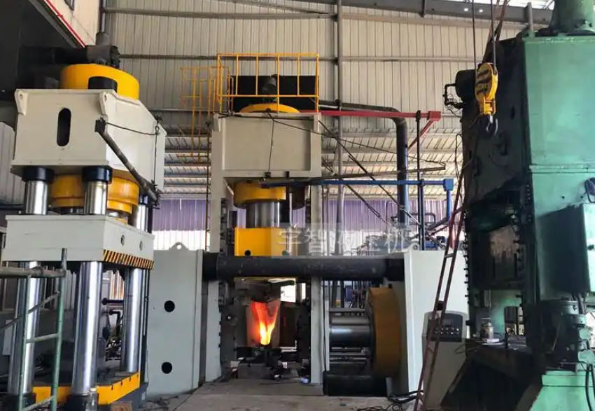
The forging tooth forming hydraulic press is the core machine in the forging tooth production process. By applying external force to the metal raw materials using this press, it causes plastic deformation of the metal, changing the shape and size of the billet while improving its internal structure and mechanical properties, resulting in the final formed forging tooth. Forging eliminates defects such as porosity generated during the metal smelting process, optimizes the microstructure, and since it preserves the complete metal flow line, the mechanical properties of forgings are generally superior to castings made from the same material. Therefore, although the forging tooth production process is costlier, it ensures the highest quality for the forged teeth. The forging tooth is a crucial component on excavators, similar to human teeth, and is an easily worn part, requiring continuous production and processing to meet demand.

Forging Tooth Forming Hydraulic Press

Forging Tooth Production Process:

The forging tooth production process includes the following steps:

  • Blanking — Heating — Pre-forging with Roller Press — Upsetting Process — Closed Die Compound Hydraulic Press Extrusion — Compound Punching and Marking Process — Post-forging Heat Treatment.

The closed-frame compound hydraulic press extrusion ensures that the forging tooth undergoes three-way compressive stress, improving the internal quality of the forging. Additionally, the compound punching and marking process reduces one step, lowers labor intensity, and enhances production efficiency.

Overview of the Forging Tooth Forming Hydraulic Press Performance and Structure:

Due to the different sizes and weights of the forging teeth, there are various tonnage models of forging tooth forming hydraulic presses. The commonly used tonnages are 1000 tons, 2000 tons, 4000 tons, and 5000 tons, with the 5000-ton forging tooth forming hydraulic press being the most commonly used. Forging presses of different sizes can forge both small and large forging teeth.

The design of the main machine structure incorporates the advantages of products from major domestic and international manufacturers, as well as advanced technology. The entire machine is optimized using finite element design and industrial design, focusing on overall performance, usability, durability, high stiffness, and reliability. At the same time, the machine's overall shape and color scheme are designed to be aesthetically pleasing.

Machine Body:

The body is composed of structural components welded from steel plates, which are vibrationally aged to eliminate welding stress. The lower crossbeam, columns, and upper crossbeam are pre-tensioned using tension rods (hydraulic pre-tensioning) to form a combined frame. The middle of the machine body is equipped with a slide, with a slanted wedge-type four-corner, eight-face guide for the slide. The slide guide plate is made of a composite material (A3+CuPb10Sn10), and the guides on the column are removable.

Hydraulic Cylinder:

The main 2000-ton downward press cylinder is implemented with a single cylinder, using high-quality 45# carbon steel forgings. The surface is treated with medium-frequency quenching, achieving hardness between HRC48-55, and is chrome-plated (5-10μm), ensuring long service life. The piston cylinder is also made of high-quality 45# carbon steel forgings, with the inner surface processed by rolling. The hydraulic cylinder provides sufficient strength and rigidity, and the main oil cylinder uses imported sealing elements to ensure reliable sealing performance.

The 2800-ton side cylinders and 200-ton top cylinders use the same manufacturing process as the 2000-ton main cylinder.

Electrical Control System:

The electrical system consists of the power circuit and control circuit. The power circuit is 380V, 50HZ, and is responsible for the starting, stopping, and protection of the oil pump motor. The core functions of the control section are handled by a programmable logic controller (PLC). Based on process requirements, commands from the main control components (such as selection switches and buttons) are processed according to signals detected by limit switches and pressure relays, driving hydraulic pilot valves and other devices to control the pressure and displacement of the hydraulic actuators (oil cylinders), thus completing the production process.

Hydraulic Control Section:

The hydraulic power system consists of the power control system, various valves, and hydraulic manipulation boxes, providing power to the main machine and enabling its control. The hydraulic station is located on the right side of the main machine.

Safety Protection Measures for the Forging Tooth Forming Hydraulic Press:

  1. Stop and Emergency Stop Buttons: In case of an anomaly, pressing the “Stop” button halts pressure and work completely. Pressing the “Emergency Stop” button will stop all operations, including the motor.
  2. Dual-Hand Operation Button: The dual-hand synchronization time limit for downward motion is 0.5 to 1 second.
  3. Hydraulic Double Support Safety Circuit: To prevent uncontrolled downward movement of the slide, a hydraulic double-support valve circuit is set in the lower chamber of the piston-type main cylinder, ensuring safety. A hydraulic interlock circuit ensures that the main cylinder piston cannot move downward unless the support safety valve is open.
  4. Overload Protection: The hydraulic system is equipped with a safety valve to ensure the press does not operate under overload conditions, thus preventing damage to the machine.
  5. Maintenance Platform: The top of the machine is equipped with a maintenance platform, ladder, and safety fencing to ensure the safety of maintenance personnel.